The battle on moisture

Didn’t have much time to work on the boat the past two weeks, but this weekend I found some time to work on the moisture problem. After some research on the net I decided to go with two measures; “insulating” the tent with a second layer and drying the air with a machine.

I found a cheap used air dryer and ordered some bubble-plastic. This is the result after a few hours of work;

I dressed the tent on the inside with lateral strokes of 1 meter wide bubble plastic. When the whole length of the tent is done I’ll join the strokes with some tape.

In the aft part of tent two more strokes are needed to cover roof and side walls. After that I’ll do the short sides.

The used air dryer. I’ve let it run some time and managed to drop the relative humidity a bit. Hopefully it will perform better once the bubble plastic is done….keep you posted!
Mounting the frames

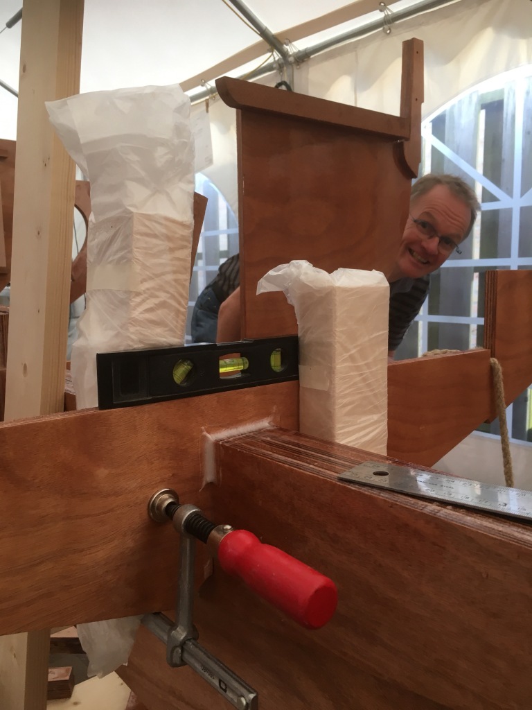
Today I mounted three frames. The first one we did was frame #3 (Roel came over to give me a hand:-). To start off we made the plan; before final fitting a layer of epoxy coating was to be applied, then the epoxy glue. Then put the frame in place and check horizontal alignment, vertical alignment and finally lateral alignment. I planned to use a thin wire attached to the stem to check for perpendicularity, but it turned out that this method is best used as a last check for blunder-detection.

After we were satisfied with the fitting of frame #3, we decided to do frames #4 and #6 in one go. That way I’ll be able to fit the longitudinal part of the support frame, which would be very helpful when fitting half frames #5.

I used a clam to temporarily fit a piece of wood. That created a slot for a wedge used to fine tune the alignment

I used a clam to temporarily fit a piece of wood. That created a slot for a wedge used to fine tune the alignment. On the picture below you’ll see I’ve been experimenting with fillets. It seemed a good idea to make one on the reachable places to better fix the frame’s position.

Too much condensation

As temperatures dropped dramatically last weekend, I found my workbench soaked after two days. Water in the somewhat warmed air had condensated against the roof and dripped down via the roof/sidewall joint.

So I spent some time researching possible solutions, but haven’t decided yet. The possible options are to mount an extra layer of plastic on the inside of the tent to “insulate” the tent, use less heat or buy a air dryer. Maybe a combination of all three will do the trick…

Lots of condensed water on the inside of the tent’s roof
Puddles on the workbench….and also one of the extension cords ceased operation 😖

Dressing the frames

After milling the frames/bulkheads to get the right fit on the back bone, it was time to work on the extra parts that have to be mounted before joining them to the back bone. There are plenty seat supports and floor battens to be fixed, and bulkhead #7 gets a sliding doors that are supported by glides with a rabbet.

Another thing that needed to be done was making the supports for the lengthened seats. Vivier’s original design features a main thwart; a rowing bench in lateral direction. As I prefer longer seats in longitudinal direction, I needed to add supports for this seat that have to be mounted on frames 5 and 6.


The starboard side of frame #6, with extra seat support.
All 4 extra seat supports; 2 for half frame #5, 2 for frame #6

It looks like a boat!

The frames/bulkheads aren’t fixed permanently yet, but I wanted to enjoy the look 😉
Half frame #5 needs support. Later I’ll mount the support frame; every station gets a temporary cross spar (hence the two holes at the tip of every frame/bulkhead) which will be interconnected by two longitudinal spars
I sanded both the back bone and the frames/bulkheads to get a nice fit

The first frame

The production of the building jig.
After putting the jig upright, I marked a straight line through the middle, so the back bone can be lined up straight.

I just copied the building jig design from one of Vivier’s building sheets. Only after it was finished and put upright I recognised it to be more suitable for another building method; frames upside down on the jig first, and then install the back bone on top. So I made a small modification to be able to put the back bone the right side up on first, and then the frames. 

Before installing the first frame, I wanted to make sure the backbone was aligned right. It has to be in a straight line laterally, the waterline has to be marked and set exactly horizontally and finally the boat’s bank angle has to be zero. I made some U-shaped brackets that hold the backbone and after some measuring and tuning I screwed those to the building jig.

Measuring a zero bank angle

After that I started working on frame number 3. The slot that is supposed to slide into the slot on the right station on the backbone is to narrow, so it had to be widened. The reason it is to narrow is that my backbone is to broad; it is composed of 6 layers of 10mm, so it should be 60mm thick in total. The size of the frame’s slot is 60mm, so that should fit. The only thing is that my back bone is thicker because I used too much epoxy during assembly, and I’ve already coated it with three layers of resin. So I used a router with copy-disk to make a nice clean, perpendicular cut (thanks, Alexander!).

Frame #3 ready for installation
Router with copy-disk to make the frame’s slot wider.

Shaving and sanding

After consulting de Bootbouwer and Francois Vivier on how to determine the right angle for the stem bevel I decided to just go ahead and shave away. The theory is that there is one angle for the whole stem, which is determined by the difference in size of the outer multiplex layer and the one adjacent. So I shaved and sanded that off, leaving a bit of flesh to fine tune once the planking is done.

On the aft part of the backbone I shaved of a piece so it is more hydrodynamic, reducing the thickness of the material from 44 to 25mm. 

The starboard side of the stem; beveled to receive planking

The aft part of the backbone. The lower extreme is reduced in thickness to be able to mount the lower rudder hinge. The rounded shape above it shows the shallow bevel allowing a higher engine screw efficiency

The taped area represents the thickness that is needed for the trailing edge of the backbone

Epoxy coating

In the past weeks I’ve been working on the frames, bulkheads and the backbone.  Before all these parts can be assembled they need three layers of epoxy resin. The quickest way to do that is to work “wet in wet”: approximately 4 hours after putting on a layer, put on the next. If done too soon or too late, the result will be inferior. Advantage of this method is that I only had to sand and defat each peace once in stead of three times.

In the next sessions I will be turning my table into a a few shelves to put the remaining wood and multiplex on. And the building frame will have to be produced as well. Oh, and another thing is that the backbone needs some work while still in horizontal position. At the back side it needs some shaving to make the part in front of the propeller more hydrodynamic efficient. And the stem needs a bevel to receive the planking, but I’m still working on a method to determine the right angle.